This is the first of several posts from my Patreon covering the build and testing of a 1581 clone, this first one from February 2024.
As part of another project I am working on, I have been testing on a variety of Commodore disk drives, and it occurred to me there was one I was missing.
I had tested 1540, 1541, 1541-II, 1570 and 1571, but I needed something that would sit between a 3½" disk and an IEC cable.

Commodore made such a thing, the 1581. Real ones of those are silly money these days. I have considered designing a replacement a few times, no doubt to be called a Mini 1581, but have always hit the problems of two out of production parts on the controller board, and the floppy drive itself.
The design is relatively simple, a 6502 processor, 8K RAM, 16K ROM, that part is easy, I can do that, but there is also an 8520 IO chip driving the IEC bus and a WD1770 disk controller.
The 8520 is out of production, and although it is a variant of the 6526, which is based on the 6522, and the 6522 is still available, the differences were too many to easily swap them without changing the firmware and making it incompatible. The WD1770 could be replaced by a microcontroller, possibly also including the 8520, but you still have the issue of a real disk drive to connect that lot to. These were standard models, all also long out of production.
I could replace the disk drive with an SD card, but then you pretty much have an SD2IEC anyway.
There are various 1581 clone designs floating around the internet. Someone who has built a couple of 1581 clones is Tim of Tim's Retro Corner. He produced two videos documenting the build and the steps required to get things working.
Tim is on my discord (see https://www.patreon.com/tynemouthsoftware), so I asked him how things were going with the 1581 drives, and which PCB design he would recommend.
He kindly offered to send me a set of the PCBs he used, and they arrived a few days later. The smaller PCB is an adapter board for PC drives, which I may or may not need.

Thanks Tim.
Thim.
This version is designed to fit into a 1581 case, or rather a 3D printed replica. I don't think at this point I am planning to do that, but we will see.
I started sorting out the parts required, which included a Commodore style power switch. I had ordered several versions of those when trying to find the best one for the Mini VIC.

The rocker on this red one was too big the VIC20 case, but will be fine here. Even if I go for a 3D printed case, I can just enlarge the switch cutout.

Mostly complete, the only bits I didn't have to hand were the ferrite beads and the EMI filters.
I did need to order a 4 pin DIN as although I am sure I have a bag of those somewhere, but couldn't find any.

Ah, that's not right. The ones Digi Key supplied seem to be this weird type with a different footprint.
Plan B.
One of the other drives I had tested was an Oceanic 118 / Excellerator Plus (repair post last month), and this had an interesting power connector.

Outwardly, it is a 5 pin DIN socket, shown here with the pin part of the plug installed so I could triple check the pinout (for reasons which will be clear if you have read the repair post).
However, the PCB appears to have been designed for a 4 pin DIN, the middle pin is missing.

You can see the pins are labelled 1,2,3,4, and not 1,4,2,5,3 as it would be on a 5 pin DIN.

I suspect they may have planned to use a 4 pin DIN, but changed to a 5 pin to avoid being too much of a blatant rip off of a 1541-II.
The standard sockets are arranged with compatible pinouts so, if you cut off the middle pin, you can solder a 5 pin DIN into a 4 pin DIN footprint.

So I did.

I added a link between the two OV pins, as only one was wired up on the PCB, not sure if that is the same as the 1581 would have had. The 0V rails on my power supply are not commoned, and are on separate wires, so I added a link on the back of the board to be sure.

That means I can use the same power cables I made for the Excellerator plus drive. (I quadruple checked the 5V and 12V rails were not transposed)

The other end was a 4 pin XLR that plugs into a 5V and 12V bench power supply I made for exactly this sort of thing. (looking back 13 years ago, I did take photos of the build but apparently didn't write up a blog post. Maybe a little late to do that now, but you never know. Watch this space.)

I didn't have any suitable 4 core cable to hand, so I braided my own. Works quite nicely.

Almost ready, just a couple of choices to make for some of the chips. The board is designed to take either a modern WDC W65C02S, or a vintage 6502. There doesn't seem to be any consideration given to the different drive levels and clock outputs on the W65C02, but all these boards seem to support both chips, so it must be OK?
It can also take a 6264 or 62256 RAM chip, although only 8K will be used with either chip.
The final choice is a WD1770 or WD1772. The later chip has extra features which are not used, but the chip can be used with a jumper change, as was done on later revisions of the 1581 itself.
I chose a WD1770, a W65C02S and a 6264, as those were the ones I had most easily available at the time.

There was one error with the PCB design to fix, the capacitor C5 is not wired up to the 0V rail, so it not doing much. I fitted it anyway so it didn't look odd.
Rather that wire that up, I went for wiring another 100nF capacitor directly to the 5V pin of the 8250 which it was meant to be decoupling the power supply for. The other end went to the nearest 0V point.

Almost time to fire it up, but I don't have a case, so I need some activity LEDs.
My first attempt was to use two surface mount LEDs.

It would have worked better with smaller LEDs, but the only ones I had to hand were 1206. 0805 would probably have been perfect.
A pair of standard 3mm LEDs worked a lot better.

Perfect, time to power on.

Red power LED, good sign. The green LED came on, and went off. Also a good sign.
Then it came back on, and then off and on and off again.
Then a gap.
Then three flashes again. And repeat.

Ah OK, this is an error signal, common on these drives. Time to check the manual.

Three flashes is bad RAM?
Odd, the RAM chip itself is fine, brand new and also tested externally, and I can't see any other problems. It also passes the zero page test every time, just failing on one of the other 31 pages.
I decided to try a 62256 instead, I soldered the blob jumper JP2. This connects 5V to pin 1 of the chip. On the 6264 this is NC, so I don't think it would be any problem to have 5V there all the time then you could fit either type of chip.

With the jumper set and the 62256 installed I tried again, but again got three flashes.

OK, time to test a theory. I had been worried before about the W65C02 option, with the timing and potentially the drive levels, maybe I should test an original 6502?

Again there are jumpers, but before I went up to the workshop to change yet more solder blobs, I thought I would double check if I could get away without changing them, just to test it out.
JP3 attaches 5V to pin 26. For the W65C02S, this is BE, Bus Enable, and needs to be pulled high (ideally with a 3K3 resistor, but direct 5V is OK I suppose). On the 6502 this is NC, so again I don't think it would be a problem to permanently tie it to 5V, specially if it were through a resistor.
The other jumper involved was JP1. This supplies 0V to pin 1. On the original 6502 this was a second ground pin. Frustratingly, the W65C02S has this an an output, Vector Pull, low when the interrupt vector is being read. Would have been nice if this had have been an input. Low to indicate "act like a real 6502", so it would act as a direct replacement when installed in a socket designed for a 6502. When pulled high, it could enable all the new features for systems designed to use them.
I tried a little test, I grabbed a few 6502 chips and stuck the meter into horseshoe mode and tested resistance between the two ground pins, pins 1 and 21, and on MOS chips, this was a few ohms. On Rockwell chips, it was about half an ohm.

Either way, I thought it would be good enough to test a 6502 with the jumpers set for a W6502S (but you couldn't do that the other way around, never plug in a W65C02S with pin 1 grounded, it is an output on that chip).
Powered on, and a single flash then off.
Sorted.
I guess that explains why all the photos I have seen of 1581 clones have used old 6502s and not the modern WDC chips.
I changed the jumpers anyway to be safe and also put back the 6264, and everything is still OK, single flash at power on.

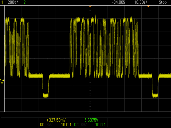
OK, power on to a single flash of the green LED. Lets connect up the IEC cables and give it a go.
I am using a C64 with an Epyx Fastload Reloaded cartridge which has a DOS wedge, to make it easier.

Nice, that looks promising.
I started with a drive freshly extracted from a working Amiga 500. That should work fine, then I can work on finding a suitable drive to keep with it.

Time to try to format a disk.
If you have seen Tim's videos (and if not, why not? go and watch them after you have finished reading this), you will recognise this error.

74 Drive not ready. OK here we go.
I was hoping to have this working in a single post (and I may go back and edit it into a single post, depending on how long it takes - edit no I didn't).

So far I am seven drives in and the best I have had is one which started to format then failed.

I have tried Amiga, PC, A3000 and ST drives, hoping I would find one that just worked, either direct or with the PC adapter. But no luck.
Tim seemed to have good results with a Samsung SFD321B floppy drives, so I have ordered one of those (which should have been here last week....).
I have also dug out a very corroded A3000 board with a VL1772 on, in case makes any difference and if it has not lost too many pins.
Update from the future
The 1581 clone is now working well, with several further posts on Patreon if you don't want to wait until next week.

Adverts
All items on my Tindie store ship from the UK, so most of the world should be unaffected by recent tariff changes, however US orders may be subject to this and handling fees etc. Please be aware of this before ordering.
There are a selection of other repair and upgrade parts for various machines, many of which can be seen on this PET 2001 board.

There are also Minstrel 2 and Minstrel 3 kits and accessories available.
You can now get a Minstrel 2 kit for $200. Same as the 1980 pricing for the ZX80 kit on which it is based.

Or if you want ZX81 compatibility, you can get a Minstrel 3 kit for $200